Sunday, September 17, 2017

The End to Summer and the Beginning of the Building Season

CNC

Every spring and summer work gets crazy as we inevitably have a big demo or milestone to complete. This, with out fail, will cause me to halt all work on all my projects until I recover from the burn out. Thankfully Fall has the opposite affect. Fall is my favorite time of years not only because of all the memories I have picking apples in our orchard and having cider pressing parties, but also because I finally get back to my neglected projects. Back in December I was super excited about building a CNC using the design for the Mostly Printed CNC (MPCNC). I bought and printed out all the parts, but that was the extent of the project.

Well over the last two days I have made some strides towards getting the CNC built. I now have the mechanical assembly completed and am ready to start wiring up the electronics. I was really impressed at how easily it went together. The instructions on the web were quite short and I thought I would have a hard time following them, but I have to say that it really was that easy to assemble. I am very impressed with the design. The only thing I am not entirely sure of is the size of it. I planned for a 24in x 24in x 4in build space. this turned into a total foot print of 34.4in x 34.4in x ~18in, which is pretty massive. Since I want to use this machine to mill my own PCBs the super large build area might actually be a hindrance as the tolerances will likely suffer, but I'll cross that bridge when I come to it, and I always have the option of making it smaller which is the beauty of this design. Below are some pictures from the mechanical assembly. I built a small platform for the CNC to sit on with a 24in x 35.5in spoil board built in (made of 1/2in particle board). That is a standard size (you just have to shorten it a bit) at Home Depot so it will make it easy to replace in the future.

X - Y Frame

Z stage added

Platform

Hardware Everywhere, But No Software In Sight

Recently at work I have been designing a lot of hardware, specifically embedded hardware. I found this very interesting and really enjoyed the design work. At the moment though we have a shortage of software positions so the progress has been pretty slow. This always frustrates me as I feel helpless to help progress the project. Also, there have been numerous times where having the person who designed the hardware also write the code would have saved a ton of time! it isn't the fault of the SW engineering that they are not familiar with the system I designed, but things could go so much quicker if I could do the work.

Therefore around three weeks ago I decided to start learning embedded design. A co-worker and good friend of mine who was our embedded expert recently moved on to another company, but left behind all the software books he had purchased while working at our company. Well one of them piqued my interest. Designing Embedded Systems with PIC Microcontrollers Principles and Applications by Tim Wilmshurst. I know sounds super exciting, right? Well normally I would agree that this sounds like a horrendous read as most technical books are very dry and I struggle to get through them. However, I have not had a problem getting into this book I am 100 pages into the 600 page book and still going strong. I found the history of PIC and the way the author laid out the curriculum very intuitive and interesting. My current plan is to keep reading and hopefully finish the book by Christmas time. I will by no means be an expert at that point, but I do think that I will be able to confidently fake my way into an embedded project at work and thus launch myself into a new position, that of the embedded system engineer. That position is as I see it a perfect fit for me. I get to design the hardware and write the code for it, what could be better? Well having an unlimited budget would be better, but alas we never get everything we want...

Saturday, December 17, 2016

Move Over Arduino, There's a Cheaper Microcontroller Option in Town

I saw this post the other day about programming a MSP430 with the Arduino IDE and was like "wait what?". My biggest problem with the MSP430 and Tiva C series microcontrollers (uCs) to date has been having to use code composer studio or IAR. Both are difficult to use, very bloated with features most of us never use, and have a very high learning curve. Pretty much every maker has used or is currently using an Arduino in a project because they are so simple to learn how to use. So if the post was right and you could code in the Arduino IDE-esque Energia IDE and then upload it to the more powerful Tiva C or far cheaper MSP430, I am totally on board.

Here is a cost breakdown

uC Cost
Arduino UNO $22
Tiva C launchpad $12.99
MSP430 launchpad $4.30
MSP430 IC $1.85

The best part is that once you buy the MSP launchpad you can use it to program a chip then remove that chip and use it in your project! So for every project after the initial it will only cost you $1.85. Now mind you the MSP430 does have some drawbacks compared to the Arduino UNO, however there are a few flavors of the MSP430 with vary levels of performance. See this post for more a more detailed comparison.

So what is the main take away here? If a MSP430 series uC will work for your project why wouldn't you use it? You save money, can use it in your own PCB or breadboard, and if you break it, no biggy just swap another one in. Now some of you may note that you can bootload your Arduino ICs and move them to a breadboard or bootload them directly in the breadboard. Well you aren't wrong, but you will need a programmer, which is an added cost. Conversely you just need the launchpad board for the MSP430.

A final word of warning. It took me about an hour to realize that the latest version of the Energia IDE no longer supported the MSP430G2231 IC, so I had to download version 17 which still did. After that it only took about 2 minutes to upload blinky to both my MSP430G2231 and my TM4C123G.

All I Want for Christmas is a CNC Machine

I love having a 3D printer. It allows me to make so many things that would just be impossible otherwise. However, there are limitations. 3D printers are slow, the plastic can be brittle, and lets face it sometimes the prints have a look that only a maker could love. So with that I decided it was time to build a CNC machine. A CNC machine is the opposite of a 3D printer, instead of extruding material to build an object it mills away material to create an object. A CNC comes with its own set of limitations, but the fact that you can mill wood, plastic, aluminum just to name a few materials will seriously up my maker game. Not to mention you can make custom PCBs.

Putting my mind to making a CNC turned out to be a fairly complicated task, so I looked for a way that I could leverage my 3D printer. A quick search on thingiverse and bingo!


Meet Mostly Printed CNC 525 "C-23.5mm OD" by Allted. This is quite the design IMHO. Basically all the red and black pieces in the above picture are 3D printed. The total print time is >100 hours. You can buy kits from his website, but I am going to print all my own parts and maybe buy the electronics/hardware from him. We will see how cheap I am feeling. I have around 95% of the parts currently printed so it is just about time to order all the other hardware/electronics.

Printing the last large piece!

My box of parts


Friday, November 18, 2016

Hot Cars and PLA Do Not Mix


As you can see, my mini-quad now has legs... So now I will be printing this again in ABS since it has a much higher melting temperature. 

Tuesday, March 8, 2016

Removable Bumpers and Sour Beers

Josh and Tim requested removable bumpers on the mini quad. This would serve two purposes, first it will allow us to remove broken bumpers and replace them, instead of replacing the whole frame. Second, we will be able to remove the bumpers which weigh 2 grams each for a total of 8 grams! This should help the flight time when we are racing.

Amy came up with the idea for how to slide the bumpers on, she's wicked smaht. Seriously though she came up with it in about a second.

Take a look below.


Pretty excited to try them out. Undoubtedly they will need some tweaking since they feel like if they are hit hard from the side they will likely pop off.

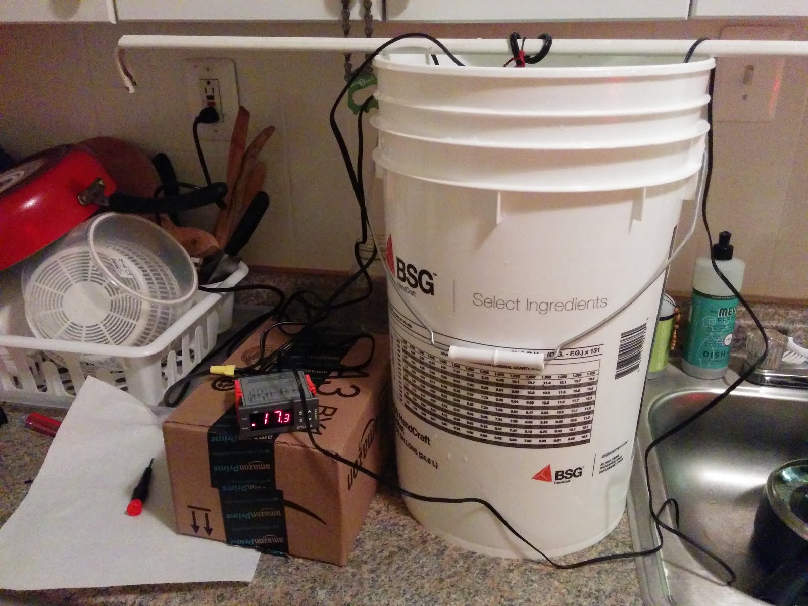
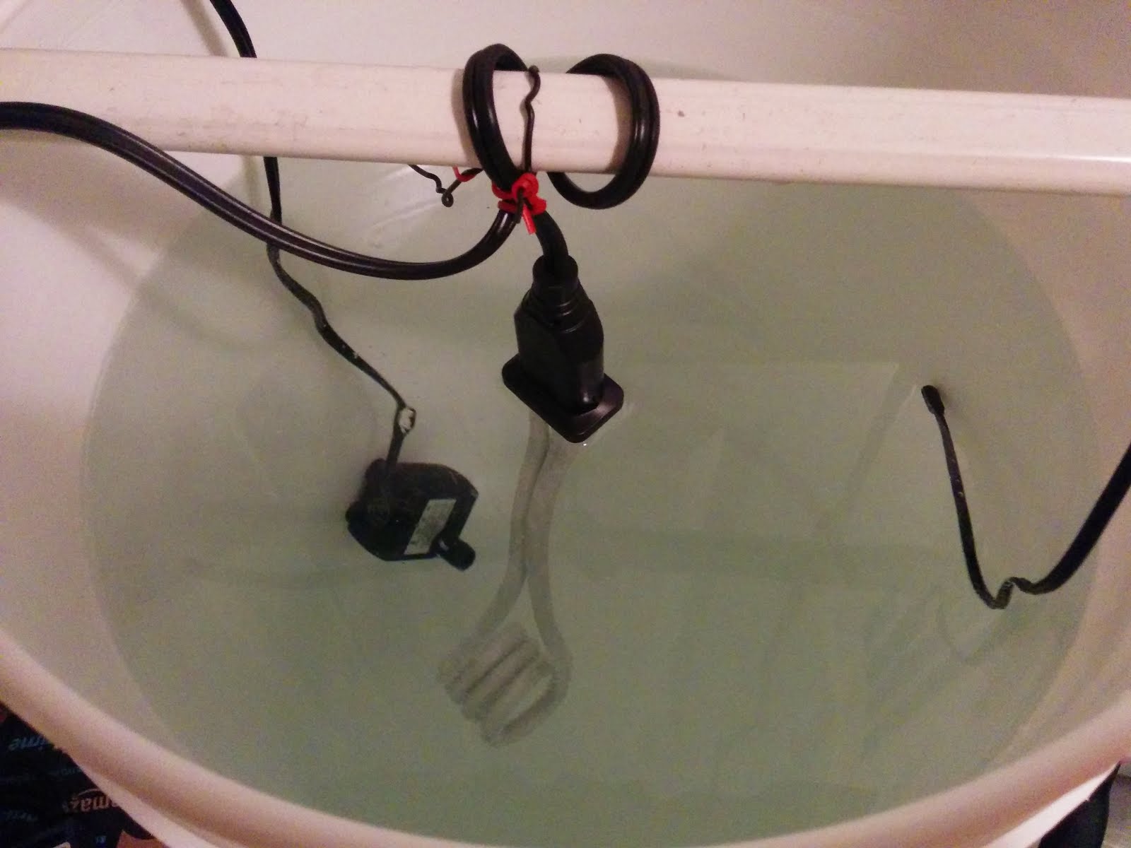
Now onto my second hobby. HOMEBREWING! I have decided to start trying to brew sour beers. Amy and I love Goses and most sour beers. I tried brewing a Gose a few weeks ago, but it did not get very sour, which was quite sad. Talking with a helpful guy at the brew store I discovered I had used the wrong bacteria, I need lactobacillus brevis in order to get the big sour flavor we like. Now in order to keep the bacteria happy during the first 3-4 days the wort needs to stay between 90F and 120F. This is pretty hard when it is winter in Boston. So I am making an immersion heater. Bascially you put the fermenting bucket in a larger bucket and then use a water heating coil with a temperature controller. I added a water pump in order to circulate the water.

Here are some pictures of my test setup.


The temperature controller has a thermistor which is also in the bucket. This allows it to sense the temperature of the water control the heating coil/pump.

Seems to be working well so far, I am excited to try it out this weekend when I start my sour beer.

Saturday, February 27, 2016

Mini Update


Josh, Tim, and I got together today and built up our mini quads. Things went fairly well except the micro multiwii FCs from hobbyking are TERRIBLE. Programming them consistently was a challenge, the GUI stinks, Tim's FC won't bind, and to top it off they stop functioning when they get cold. We tried to fly outside in 35F weather, apparently that was too cold since they literally wouldn't communicate with the transmitter, but were fine after being back inside for a few minutes.

So we are looking to upgrade out flight controllers to something more reliable.

Flight Controller (might have them made myself if I can get them cheap and we can solder them)
Orange T-Six Receiver
Taranis x9d Recevier (Need to double check, but this would mean Tim does not need to buy a module for his transmitter)

I was unsure what CPPM was or if the lulfro FC supported it (it says PPM). This forum topic helped clear that up. "It's actually just PPM, CPPM seems to be a name dreamed up just to differentiate PPM output from the Rx on a servo port from the PPM output of the Tx to the module or DSC port.".

Also we could potentially get rid of the video battery since these boards have a filtered regulated output for FPV gear (it is 5V but can be switched to 3.3V)

Last update is the frame got an upgrade and it works pretty well. Still some tweaking to do, but it works well for now.

Saturday, February 20, 2016

The Mini Quad

So I kind of built it before posting anything... Sorry. It has been crazy the last few weeks, which is partly why it has not gotten finished before now and partly why I have not posted anything while I was building it.

Also this is a good resource for micro quad stuff


Bill of Materials

Micro MWC FCB DSM2FC/ESC/RX1$36.00
USB FTDI Flash StickFTDI1$8.10
Quanum Pico 32bit FCBFC upgradeN/AN/A
8.5x20mm MotorMotors2$2.99
600TVL 1/4 1.8mm CMOSCamera1$9.99
Boscam FPV 5.8G 200mWVideo TX1$11.00
Walkera 350mAhflight battery2$3.99
Video Batteryvideo battery1$2.62
Chargercharger1$2.50
Video TX DiodeDiode1$0.34
2 Pin 6 x Pico PlugPico plug2$0.50
small custom antennaantenna1$0.00
Hubsan X4Props3$1.50
2 Pairs 2627Other Props2$1.82
Quad FrameFrame1$0.00
JST Connectors (1 male, 3 female)Amazon4$0.50
Shipping1$15.00
Boscam 5.8Ghz 200mW RXVideo RX1$17.00
Fat Shark RC Vision Systems NexWave RF,Goggle RF1$30.00

Hardware

Read through all notes in this section before assembling/soldering things.
I suggest you assemble the quad without cutting wires first, then measuring wires to make your connections to the flight controller board, battery, etc. You don't want things to be too short or too long.

NOTE: Do not put the male JST on the flight controller (FC) board (as shown in this picture). Use the Female JST.
NOTE: Do not put the female JST on the battery (as shown in this picture). Use the male JST.

What the V1 quad looks like when assembled


Motor layout. You want the red/blue motors diagonal from each other, and the white/blue motors diagonal from each other.

Video System

Be extremely careful soldering to the video transmitter. The pads can get to hot and rip off really easily.

Camera wiring. The camera antenna wire is just motor wire (the red on the wire is insulation). Cut it to be exactly 12.92mm (this is the length needed for 5.8GHz)

The bulge on the red wire in the above picture is the video TX diode mentioned in the BOM above. This is required so that you can fully charge the flight battery and use it with the video transmitter (we are dropping voltage across it so the video TX doesn't get to hot). The video TX requires 3.3V and the battery is 4.2V fully charged. The diode has a forward voltage drop of 0.36V so the voltage that the video TX gets when the battery is fully charged is 4.2V-0.36V = 3.84V. This is still high, but it can handle it. Install the diode with the anode on the battery side of the red wire and the cathode on the video TX side of the red wire (so current flows).

I hot glued wires down to prevent then from ripping off and to add some strain relief.


Use some hotglue if the motor feet or the FC holder feels too lose. If the motors feel to loose you can add a little hot glue to the outside of the motor where it meets the 3D printed material.

Calibrate the Electronic Speed Controller

There are videos on youtube, but they all stink and don't really show you how to do it for our boards. If your motors all start to spin at different times then we will have to calibrate the ESCs. We can figure it out when the time comes.

Software

First download MultiWii GUI from my github 
next download the arduino code from my github

Next follow along with this video MultiWii Setup
MultiWii Resource

I don't think it actually matters what screen you are on in arduino when you upload the code, but I am always on the multiwii.cpp

After uploading the code you can use the GUI for final configuration (the video does a pretty good job explaining how to set things up). I set my quad to arm/disarm with an aux switch on my Orange T-six transmitter.

Arduino IDE Settings


Use the pogo stick after the code has compiled and is attempting to upload. The ftdi programmer red and green leds should start flashing fast and you should see an uploading notification in the arduino console.

Transmitter


I created a miniquad profile on my Orange T-Six for this quad so that it is different than my large quad. I suggest you do the same.

Settings


ESC Calibration

Config.h is where the code you must uncomment is located.


https://www.youtube.com/watch?v=eA8jjCqbKZY

Wednesday, November 4, 2015

1st Quad Race

Took my lunch break with two of my coworkers yesterday and went over to the field near our work. My coworker Jim had just finished his custom designed quad and was trying it for the first time. Murphies law obviously made an appearance and it took us some time to debug the couple issues that were present. After that his quad had a short flight and then took a hard landing completely breaking the frame. He'll 3D print a new one and be ready to go in no time though.

My other coworker Matt and I decided to have a race on our second battery pack. We did a 3 lap race up and down the field. I had a ton of fun and was surprised how well I was able to keep it low to the ground. I should mention that I decided to change the PI gains around a bit for the second flight and that really helped. I had set them back to default for the first flight and had the same problems with wobble that I had been having. I turned the gains down a bit and wow did it make a difference. Obviously I didn't tune them, but just that little change really helped. I will have to take some time and tune them properly soon. The new PID gains are as follows.


The battery on the bottom of the quad worked out fine and seemed to have no effect on the flight characteristics. Looking forward to another race on Thursday.

Tuesday, November 3, 2015

Battery Woes

I have not had great luck with batteries recently. My troubles started when I took a hard landing and my rear arm broke resulting in a prop strike to my battery pack, see below.


Next problem I encountered was when I was doing my preflight and discovered that the battery in my transmitter was dead. Apparently the transmitter was switched on in the case and this drained the battery all the way to zero causing it to puff up, see below. At this point both batteries are toast. I had thought that the transmitter had a safety feature that would cut power if the battery got too low, but I guess not.


In order to prevent this in the future I am going to do two things. One, I will relocate the quad battery to the bottom of the quad. Two, I will always unplug the transmitter battery after flying. Looks like I need to write pre-flight and post-flight checklists...


Wednesday, October 14, 2015

More Flights = More Learning Opportunities

Went back to PA for the weekend and got to fly a couple times. I tried flying at my house because some people wanted to see me fly. Against my better judgement I said yes. Besides being a small area, there are a bunch of trees... So as you can imagine it almost ended in disaster. Thankfully the drone gods smiled on me and I somehow flew through a bunch of branches and landed safely. After that I went to my old elementary school, which is now vacant, and got some great flights in.

I am still noticing a wobble when flying, and it is starting to become a problem. So I started adjusting some settings. I first turned down the roll and pitch full through limit to 45 degrees so the sticks wouldn't be so sensitive. Next I adjusted my PID settings. I turned my attitude Kp value down, and set the Ki setting to slightly below it (set rate Ki and Kd to zero). Unfortunately it was really windy tonight when I tried out the new setting and was getting dark so I crashed and it broke my bottom plate, guess I will have to print that part with a higher infill. I'll have to try to tune this when there is no wind. I also noticed that the rear left motor seems to not spin when all the other motors start spinning. This is a problem since the quad wants to flip when it takes off until the motor spins up to the other motors speed.

So basically I've got some adjustments to make. Sounds like my next flight is going to be a lot of short take offs followed by landings for adjustments.

Friday, October 9, 2015

Second Flight


Decided to go for a flight on Wednesday after work. Went to a local field (Browning Fields). The weather was great, pretty much zero wind, warm, and sunny. I had two of my props on backwards, oops. I forgot to move the props around with the motors after I changed their mounting orientation. After that quick fix I did a short line of sight flight to make sure nothing else was wrong, with that test passing I set up my FPV gear and started my first flight of the afternoon.

Up until this point I had pretty much only flown FPV in a simulator for about 3 hours, so I had a little experience. My last flight was all line of sight and involved a lot of crashes (the field was also really tiny). So I was a little nervous jumping right into using my FPV goggles, but I am really glad I did. Flying in FPV was soooo much easier than line of sight. All the controls were as you expected (ie you don't have to reverse your controller movements when the quad is flying at you). I had two short 3 minute flights followed by two longer 6 minute flights. On each flight I felt very in control and had zero crashes. Overall a great day.

Some things I noticed were that the yaw control was very very sensitive, and the PID control loop on my flight control was in need of some tuning. Every once in a awhile the quad would start shaking back and forth for a few seconds making it very hard to control. So I think before my next flight I will try to tune the controller a little bit.

Here is a video from one of my flights.


Let the Modifications Begin!

After the first flight I had some modifications I wanted to make in order to improve the quad.

Added a JST connector and soldered on a new XT60 cable since the old one was cut by the prop

Motors in the correct positions now

New cable management plan

Moved video TX forward by drilling a new hole

Battery connector out the back protects the cable from prop strikes

Completed Modifications


Added a 10mm white LED in the front and a 3mm red led in the back

ESC wires are now coming out the bottom of the quad and then up onto the arms


JST connector for 8V to top plate electronics

Receiver moved up front


Thursday, September 17, 2015

Wasp's Maiden Flight

Maiden Flight


On the first flight I accidentally got up to around 200 feet, and that was almost the end of Wasp. Thankfully I was able to get it back down and not crash into a tree. Pretty lucky. The only thing that broke was one prop. After my first crash the dampers were pulled out of the top and bottom plates (basically the dampers got ripped out of the plates), so it is really important to zip tie through all of the dampers.


Quads and a helicopter gathered before we fly


Lessons Learned

  1. Motors are mounted in wrong arrangement rotate them CW by one position 
  2. Move battery to bottom, print cage 
  3. Move discharge wire out of the way 
  4. Tighten arm bolts 
  5. Focus camera properly 
  6. Adjust PID gains? 
  7. Wire in JST connectors 
  8. Print spare parts 
  9. Buy more props 
  10. Use antenna on headset with correct polarity SMA connector 
  11. Zip tie through all of the dampers
#1 
As I mentioned in The Build Part 1 the motors are labeled in a non-intuitive way (labeled CW wrt to the threads, not the rotation of the motor), so I mounted them in the wrong positions, oops. In this orientation the locking nuts on the props will loosen during your flight, eventually the props will come off and you will be flying a rock.

#2
Moving the battery to the bottom of the quad will help make the flight characteristics more stable, and keep it away from the blades (in case you crash and the arms fold in)

#3
I want to reroute the discharge wire to come out the back of the quad. I had a few crashes where the arms folded back in and the still spinning props actually cut the discharge wire, not good.

#4
The arms felt like they folded in too easily, so I want to tighten the bolts.

#5
The camera was out of focus for objects far away. If I want to fly FPV I need to fix that.

#6
All settings were default, so I want to adjust those to improve stability during flight.

#7
I had to solder all the wires directly to each other. I want to replace those connections that can be with JST connectors.

#8
With all the crashing I'm going to need some spare parts.

#9
Definitely will be needing more props.

#10
The antenna on the headset had the wrong polarity, so there was no pin between the antenna SMA and the SMA on the headset.

#11
As I mentioned zip ties through the dampers are really important so that when you crash the plates don't pop off the dampers.